CIS-261 Home http://www.c-jump.com/bcc/

Modes of Memory Addressing on x86


  1. Two Real modes of addressing on 80x86
  2. Segment Registers
  3. Real Mode Segmented Model
  4. Real Mode Segmented Model, Cont.
  5. Problems Related to Segmentation
  6. Address Space in Real Mode
  7. Collective Terms for Memory
  8. Memory Paragraphs in Real Mode
  9. Segment of Memory in Real Mode
  10. Memory Access in Real Mode
  11. Segment Registers in Real Mode
  12. Segment Register Names
  13. Segment Register Names, Cont.
  14. Segment Positions in Real Mode
  15. General-Purpose Registers in Real mode
  16. Segmentation Models Summary
  17. Real Mode Flat Model Summary
  18. Real Mode Flat Model Diagram
  19. Real Mode Segmented Model
  20. Real Mode Segmented Model, Cont.
  21. Real Mode Segmented Model, Cont.
  22. x86 Protected Mode Flat Memory Model
  23. Advantages of Flat Memory Model
  24. The Protected Mode Flat Model Diagram
  25. The Protected Mode Flat Model Diagram, Cont.
  26. The Protected Mode Flat Model Diagram, Cont.
  27. Protected Mode Flat Model Summary
  28. Console Applications
  29. Segment Registers in Protected Mode
  30. Protected Mode Architecture
  31. Rings of protection, four levels of security
  32. Three types of segment descriptor tables
  33. Flat vs. Segmented Memory Model
  34. Differences between 16-bit and 32-bit Memory Modes
  35. Differences, cont.
  36. Differences, cont.
  37. Older OS and Addressing Modes Compared

1. Two Real modes of addressing on 80x86


2. Segment Registers

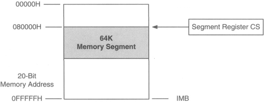
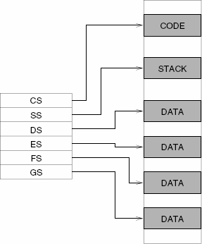
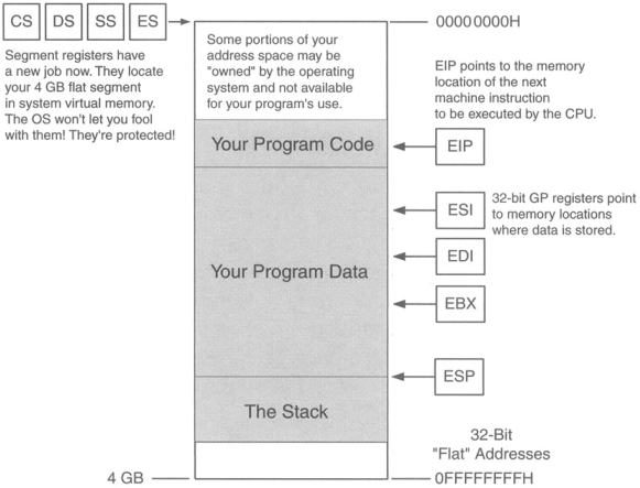
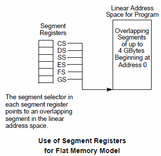
  • Segment registers are basically memory pointers located inside the CPU.

  • Segment registers point to a place in memory where one of the following things begin:

    1. Data storage

    2. Code execution.


  •  

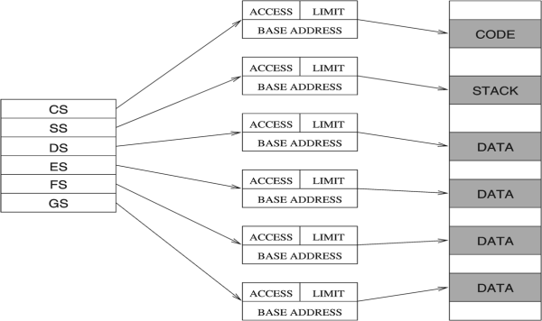
  • Example: code segment register CS points to a 64K region of memory:

      code segment register

3. Real Mode Segmented Model


4. Real Mode Segmented Model, Cont.


  • Addresses are limited to 20 bits:

    • 220=1,048,576 bytes.

  • Physical address is generated by adding a

    • 16-bit segment register, shifted left four bits

    • plus a 16 bit-offset.

  • Generating 20-bit physical address in Real Mode:

      Generating 20-bit address in Real Mode


5. Problems Related to Segmentation


6. Address Space in Real Mode


7. Collective Terms for Memory


8. Memory Paragraphs in Real Mode


9. Segment of Memory in Real Mode


  • Every byte of memory, accessible by program, is assumed to reside in a segment.

  • Segment size varies and can range from 1 byte to 64 Kbytes.

  • Nothing is protected within a segment in Real Mode.

  • Segments can overlap.

  • Initializing the data segment register in 16-bit real mode:

  • Numerical (immediate) values cannot be moved directly into the segment register. It is a 2-step process:

        mov ax, 1000h
        mov ds, ax
    
  • Initializing the data segment register:


      Initializing the data segment register


10. Memory Access in Real Mode


  • Recall that 8086 and 8088 CPUs had 20 address pins, limiting a program to 1 megabyte of memory.

  • To express a 20-bit address, two 16-bit registers are used:

    • segment address in one 16-bit register,

    • and the offset address in another 16-bit register.

  • The memory location of a particular byte from one megabyte of memory is calculated as

    • segment start address

    • plus distance between the byte and the segment start.

  • The byte's distance from the start of the segment is referred to as the byte's offset address.

  • SEGMENT:OFFSET addresses are always written in hexadecimal notation.

    • For example, an address of one byte of data MyByte is given as 0001:001D.

    • This means that MyByte is in segment 0001H and is located 001DH bytes from the start of that segment.

  • Since segments can overlap, same byte could also be located by SEGMENT:OFFSET combinations 0002:000D or 0001:001D.

  •   segments and offsets

      Generating 20-bit address in Real Mode


11. Segment Registers in Real Mode


12. Segment Register Names


13. Segment Register Names, Cont.


  • FS and GS are clones of ES, the extra segment.

  • FS and GS both are just additional segments, no specialty here.

  • Names FS and GS come from the fact that they were created after ES: E, F, G.

  • They exist only in the 386 and later x86 CPUs.

  • Extra segments ES, FS, and GS can be used for both data or code.

  • The six segments of the memory system:

      The six segments of the memory system


14. Segment Positions in Real Mode


15. General-Purpose Registers in Real mode


  • General-purpose registers may hold

    • data values

    • offset addresses that must be paired with segment addresses to locate data in memory.

  • The customary notation is to separate the segment register and the offset register by a colon. For example:

        DS : AX
        SS : SP
        SS : BP
        ES : DI
        DS : SI
        CS : BX
    
  •   The real mode segmented model


16. Segmentation Models Summary


17. Real Mode Flat Model Summary


18. Real Mode Flat Model Diagram


  • The segment registers are all set to point to the beginning of the 64K block of memory.

  • The operating system sets segment registers when it loads the program.

  • All segment registers point to that same place.

  • Physical segment assignments never change as long as the program is running.

  • The segment registers are still functioning, but no work with segments is required.

  •   The real mode flat model


19. Real Mode Segmented Model


  • Real mode segmented model was mainstream programming model throughout the MS-DOS era.

  • Used when Windows 9x machine is booted into MS-DOS mode.

  • Good choice to write code to run under MS-DOS.

  • Program has access to 1MB of memory.

  • The CPU handles transformations of segment:offset combinations into a full 20-bit address.

  • CS always points to the current code segment

  •   The real mode segmented model


20. Real Mode Segmented Model, Cont.


  • The next instruction to be executed is pointed to by the CS:IP register pair.

  • Machine instructions called jumps can change CS to another code segment if necessary.

  • The program can span several code segments.

  • There is no direct CS manipulation to change from one code segment to another:

    • when a jump instruction needs to take execution into a different code segment, it changes CS value for you.

  •   The real mode segmented model


21. Real Mode Segmented Model, Cont.


  • There is only one stack segment for any single program.

  • A program has potential to destroy portions of memory that does not belong to its process.

  • Careless use of segment registers will cause the operating system to crash.

  •   The real mode segmented model


22. x86 Protected Mode Flat Memory Model


23. Advantages of Flat Memory Model


24. The Protected Mode Flat Model Diagram


  • The instruction pointer is 32 bits in size

  • EIP can indicate any machine instruction anywhere in the 4 GB of memory.

  • The segment registers still exists and define where 4 GB of program-accessible memory resides in physical or virtual memory

  • The segment registers are now considered part of the operating system, you can neither read nor change them directly.

  •   The protected mode flat model


25. The Protected Mode Flat Model Diagram, Cont.


  • When 32-bit program executes, it has access to 4-gig address space.

  • Any general-purpose register by itself can specify any memory location in the entire memory address space of the 4 billion memory locations

    • (except certain operating system-specific parts of the program that belong to the operating system.)

  •   The protected mode flat model


26. The Protected Mode Flat Model Diagram, Cont.


  • Attempting to actually read or write certain locations in your own program can be forbidden by the OS and will trigger an error.

  • Challenges in programming for protected mode flat model are based on understanding the operating system, its requirements, and restrictions.

  •   The protected mode flat model


27. Protected Mode Flat Model Summary


28. Console Applications


29. Segment Registers in Protected Mode